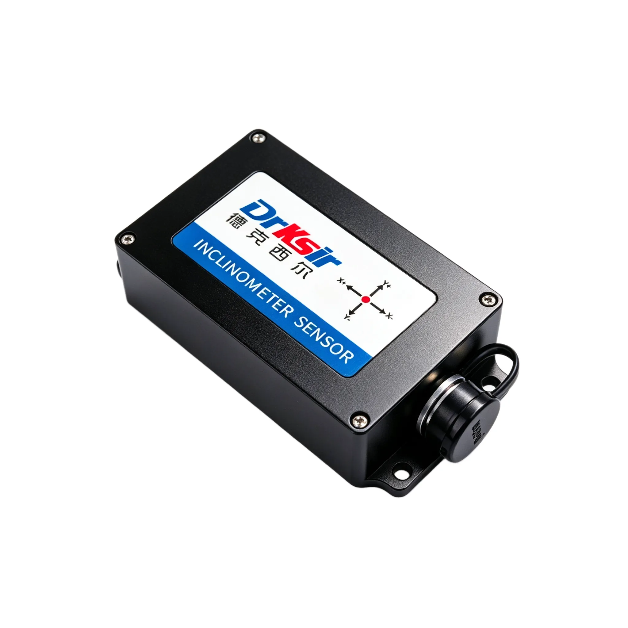
When an engineer emails me asking, “The sensor reads 0.3°, but my drawing shows the pier moved 12 mm — which one is right?” my answer is always the same: both, once you convert. A tilt sensor reports an angle. Your structural report, your machine spec, and your acceptance criteria are almost always written in millimeters or inches. The gap between those two units is exactly where most field mistakes happen. This guide shows the formula, walks two real examples, and lists the unit traps that wreck data.
Why Angle Alone Doesn’t Tell the Whole Story
A 0.1° tilt on a 10-meter reference arm is about 17 mm of movement at the far end. The same 0.1° on a 100-meter span is 174 mm. The angle is fixed; the displacement scales with distance. That is why “what angle do I see” and “how far did it move” are two different questions, and you usually need the second one answered before sign-off. Our inclinometers bind angle and distance together in the same installation, so you can report both from one sensor.
The Small-Angle Formula
The geometry is a right triangle. Displacement L equals the reference distance D times the tangent of the tilt angle θ:
L = D × tan(θ)
For angles under about 5°, tan(θ) is almost equal to θ measured in radians, so the formula collapses to:
L ≈ D × θ_rad
And the bridge between units is:
θ_rad = θ_deg × π / 180
A handy constant: 1° = 17.45 milliradians. So a 0.01° tilt equals 0.1745 mrad. Multiply that by your distance D in millimeters and you have the displacement in millimeters. Keep every term in the same unit and the math stays clean.
Worked Example 1 — Bridge Pier Deflection
Suppose a bridge pier cap tilts 0.01° and your monitoring point sits 5 m from the rotation axis.
L = 5000 mm × tan(0.01°) = 5000 × 0.0001745 = 0.873 mm
A 0.001° sensor would resolve that to 0.087 mm — ten times finer. Here is the same angle at several distances:
| Tilt angle | At D = 2 m | At D = 5 m | At D = 10 m |
| 0.001° | 0.035 mm | 0.087 mm | 0.175 mm |
| 0.005° | 0.174 mm | 0.436 mm | 0.873 mm |
| 0.01° | 0.349 mm | 0.873 mm | 1.745 mm |
| 0.05° | 1.745 mm | 4.363 mm | 8.727 mm |
| 0.1° | 3.490 mm | 8.727 mm | 17.45 mm |
Notice how the same 0.01° becomes sub-millimeter at 2 m but nearly 2 mm at 10 m. Distance is doing half the work, which is why you should never quote a tilt reading without the distance it was measured across.
Worked Example 2 — Crane Boom Tip Drop
A 30 m crane boom pitches 0.5° downward. How far does the tip drop?
L = 30,000 mm × tan(0.5°) = 30,000 × 0.008727 = 262 mm
That is a quarter of a meter — enough to miss a load target by a wide margin. A sensor with 0.01° resolution reports this movement in clean 5 mm steps, which is plenty for a boom this long. The same 0.5° on a 3 m arm is only 26 mm, where you would want finer resolution to stay useful.
How to Pick the Right Reference Distance
The single biggest source of wrong displacement numbers is a sloppy reference distance D. D is the distance from the rotation axis to the point where the sensor is mounted, not the total length of the structure. On a bridge, the axis is usually the bearing or the pier base. On a crane boom, it is the pivot. Measure D from that axis to the sensor, not to the far end of the member. If you mount the sensor 2 m from the pivot but report the result as if D were 10 m, every number you log is five times too large. When in doubt, sketch the triangle, mark the axis, and measure twice. A cheap tape measure at installation saves a costly redesign later.
Logging the Result the Right Way
A conversion is only useful if someone can repeat it next month. When you record a reading, write the angle, the unit (degrees, not radians), the reference distance D, and the resulting displacement together — on the same line. Note the temperature too, because thermal expansion changes the real geometry independent of tilt. Tag the log with the sensor serial number so a future audit can trace the number back to the exact device. The engineers who inherit your data will not know your mental shortcuts; the logbook has to.
When the Small-Angle Trick Stops Working
The shortcut L ≈ D × θ_rad is accurate to within 0.4% for angles under 5°, and within 1.5% under 10°. Past that — think ±30° or ±60° inclinometers on steep machinery — use the full L = D × tan(θ). At 30°, the small-angle version overstates displacement by about 4.7%. Not huge, but it will fail an acceptance test that was built on the simplified formula.
Three Conversion Mistakes I See in the Field
1. Degrees vs radians in the spreadsheet. Excel’s TAN() expects radians, so wrap your angle with RADIANS(). Feed it degrees directly and every result is wrong by a factor of 57.
2. Resolution, not accuracy. A 0.001° accurate sensor is useless if its resolution is 0.01°. To catch a 0.5 mm movement at 10 m you must resolve 0.0029°, so you are in the 0.001° tier, not the 0.01° one. Check the datasheet’s resolution line, not just the accuracy headline.
3. Forgetting the reference distance. The same angle gives wildly different displacements at different D. Always write D next to the angle in your logbook, or the number means nothing a week later.
Choosing a Sensor That Resolves Your Movement
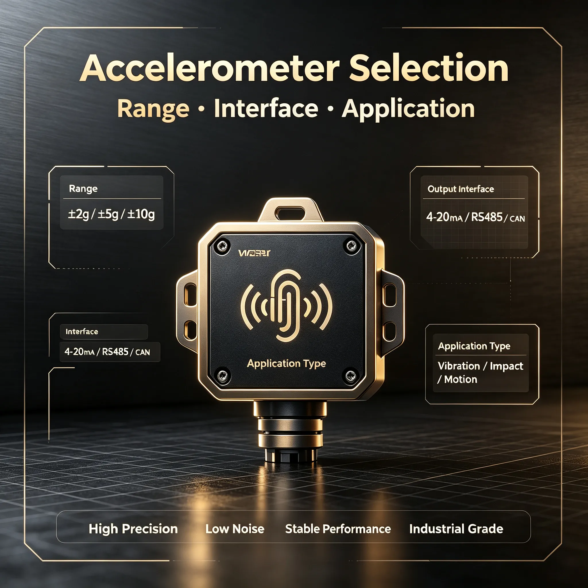
Work backwards. Decide the smallest displacement you must detect, pick a reference distance D, and divide: θ_min = L_min / D. If that comes out at 0.0029°, a 0.01° sensor will not see it and you need the 0.001° tier. Our guide on how to choose inclinometer accuracy walks through the four tiers and where each one fits. For structural work at the finest end, the DR-INC-500 series ships with 0.0005° resolution and supports both RS485 and 4-20mA output to match your controller.
Wrapping Up
Angle and displacement are two views of the same tilt. Convert with L = D × tan(θ), keep your units straight, and size the sensor from the movement you actually need to catch. Run the numbers on your own setup, and if you want a second pair of eyes on the sensor choice, contact us with your distance, angle range, and interface.
📧 Email: sales@drksirsensor.com | 💬 WhatsApp: +86-135-1581-0281