Picking the right industrial accelerometer is less about finding the “best” sensor and more about matching one to the machine in front of you. Engineers usually come to us with a symptom — a motor that sounds wrong, a tower that sways, a press that kicks — and the job is to translate that into three numbers and one interface. This guide walks through how to choose an industrial accelerometer without overspecifying it, or worse, clipping the very signal you are trying to catch.
Start with the measuring range
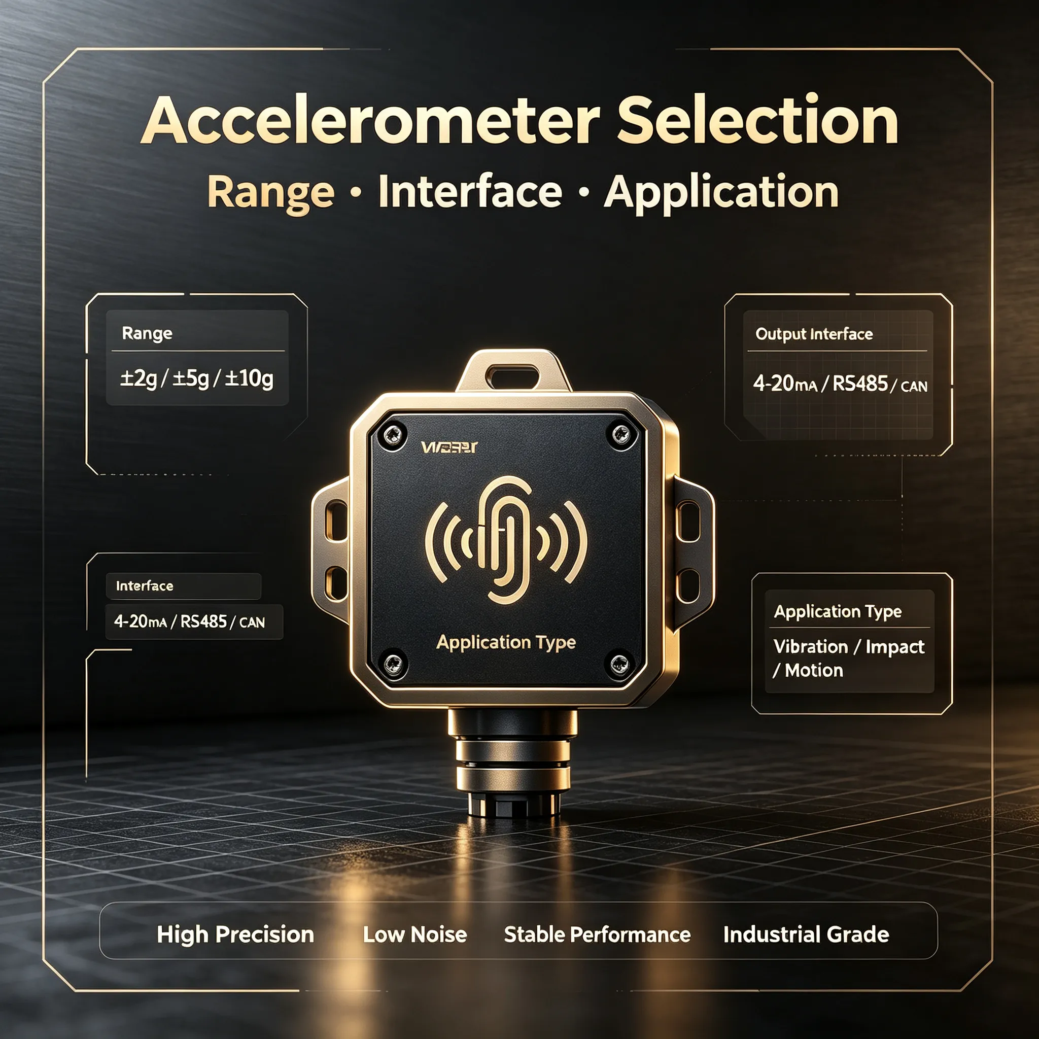
The single most common mistake is choosing a range that is too large. Resolution is a fixed fraction of full scale, so a sensor specified ten times too big quietly throws away the detail you paid for. As a working rule, your normal operating acceleration should sit at roughly one-third to one-half of the full range, leaving headroom for start-up transients and fault events without wasting resolution.
| If your signal normally sits at | Choose | Built for |
| Below 1g (tilt, slow structural movement) | ±2g accelerometer | attitude sensing, wind-tower sway, bridge low-frequency vibration |
| Low single digits of g (motors, pumps, fans) | ±8g accelerometer | machine vibration monitoring, predictive maintenance |
| Several g with regular shock (excavators, AGVs, presses) | ±16g accelerometer | construction machinery, rail vehicles, stamping presses |
| High-g impact (drop, crash, forging tests) | ±32g accelerometer | impact testing, packaging qualification |
All four share one mechanical platform — 0.01g absolute accuracy, 0.001g resolution, 3-axis, IP67/IP68 and a −40 to +85 °C range — and sit together in our industrial accelerometers range. Move up a step only when you actually see the peaks; moving up “just to be safe” costs you resolution you will never get back.
Count the axes you need
A triaxial accelerometer measures X, Y and Z at once, which means one mounting point captures the full motion vector. For rotating machinery that is almost always what you want — a fault rarely announces itself on a single axis. Our entire range is built 3-axis for exactly this reason; you are not paying extra for axes you will use. If you only ever watch one direction and mounting space is tight, a single-axis unit can work, but for condition monitoring the triaxial version pays for itself in installation time alone.
Pick the output interface
The output decides how the sensor talks to the rest of your system, and the right answer depends on what is already there:
- CAN — for vehicles and mobile machinery where a bus already exists. Our CAN version is in stock now, samples at 100 Hz, runs on 9–36 V DC, and is the easiest fit for off-highway equipment.
- 4-20mA — for long cable runs and direct PLC/SCADA input, immune to noise over distance.
- RS485 (Modbus RTU) — when you want many sensors on one digital network.
- 0-10V — short, cost-sensitive runs.
The 4-20mA, RS485 and 0-10V variants are available on request; tell us your controller and we will confirm the build.
Don’t overlook accuracy, environment and build
Accuracy and resolution set what you can see. Across the range we hold 0.01g absolute accuracy and 0.001g resolution, which is enough to trend bearing wear long before it becomes audible. For the environment, IP67/IP68 (customizable to your washdown or outdoor need) and −40 to +85 °C cover most plants and field sites. Each unit ships with a 1.5 m shielded cable, weighs 220 g, and is rated for 55,000+ hours of service life. If your application is static tilt rather than running vibration, our inclinometers will usually serve you better — an accelerometer is the wrong tool for a slowly changing angle.
A quick selection checklist
- Normal acceleration? Pick a range with roughly 2–3× headroom.
- One direction or full vector? 3-axis for machines, single-axis only when space forces it.
- What does your controller accept? CAN in stock; 4-20mA / RS485 / 0-10V on request.
- Indoor panel or harsh field? IP67/IP68, −40 to +85 °C across the board.
- Tilt or vibration? Tilt → inclinometers; vibration → accelerometers.
Sampling and bandwidth: how fast is fast enough
Resolution and range get most of the attention, but sampling rate decides whether you can see the fault at all. For the bulk of plant machinery — motors, pumps and fans running up to a few thousand rpm — a 100 Hz sample rate comfortably captures the rotation frequency and its harmonics, which is where the faults you actually chase show up. Our CAN-version accelerometers run at 100 Hz, covering those fault frequencies with margin. Very high-speed spindles or fine gear meshes are a different case; tell us the shaft speed and we will tell you whether the standard build fits or you need a faster configuration.
Frequently asked questions
How do I know if I am over-ranged? If your readings keep hitting the rails, you need more range. If the trace looks flat and quiet, you are probably over-ranged the other way and losing resolution — drop down a step.
Can the sensor be customized? Yes. Range, output, cable length, connector and housing are all configurable, and we run OEM/ODM batches.
What if I am not sure which range fits? Send us the machine type, running speed and mounting position and we will size it for you — for the program side of this, see our guide to vibration monitoring with accelerometers.
Get a quote
Choosing the range is half the job; mounting and cabling are the other half. Contact our engineers with your machine details and we will come back with a recommendation and a quote. 📧 sales@drksirsensor.com 💬 WhatsApp: +86-135-1581-0281