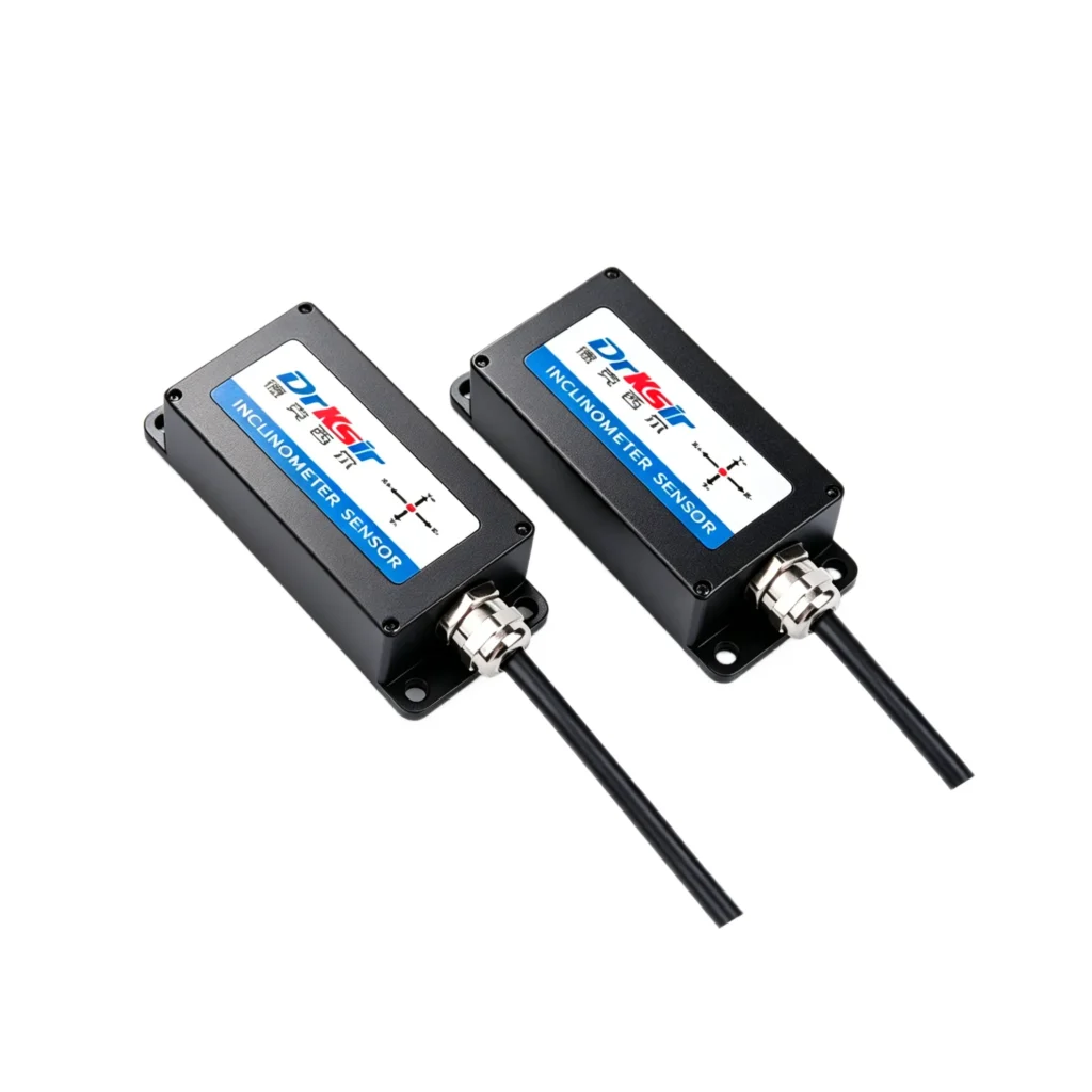
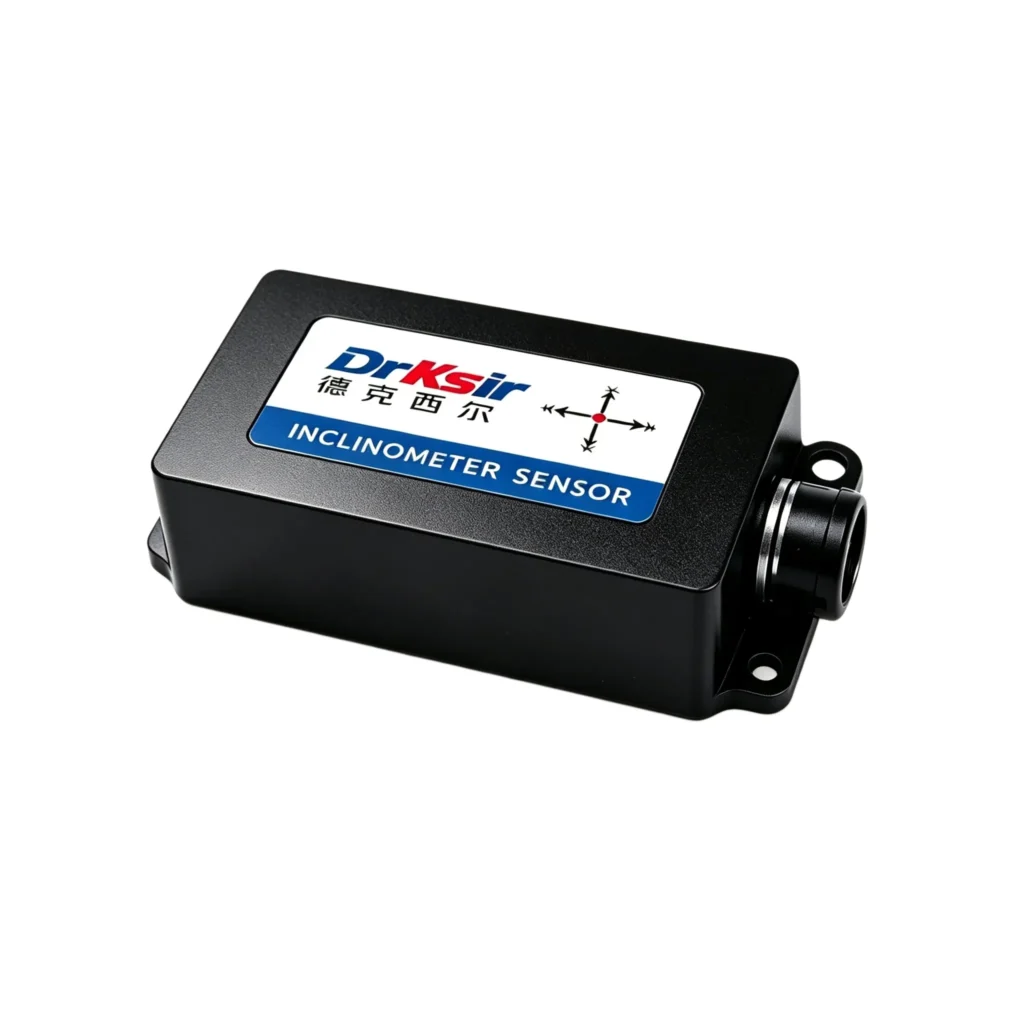
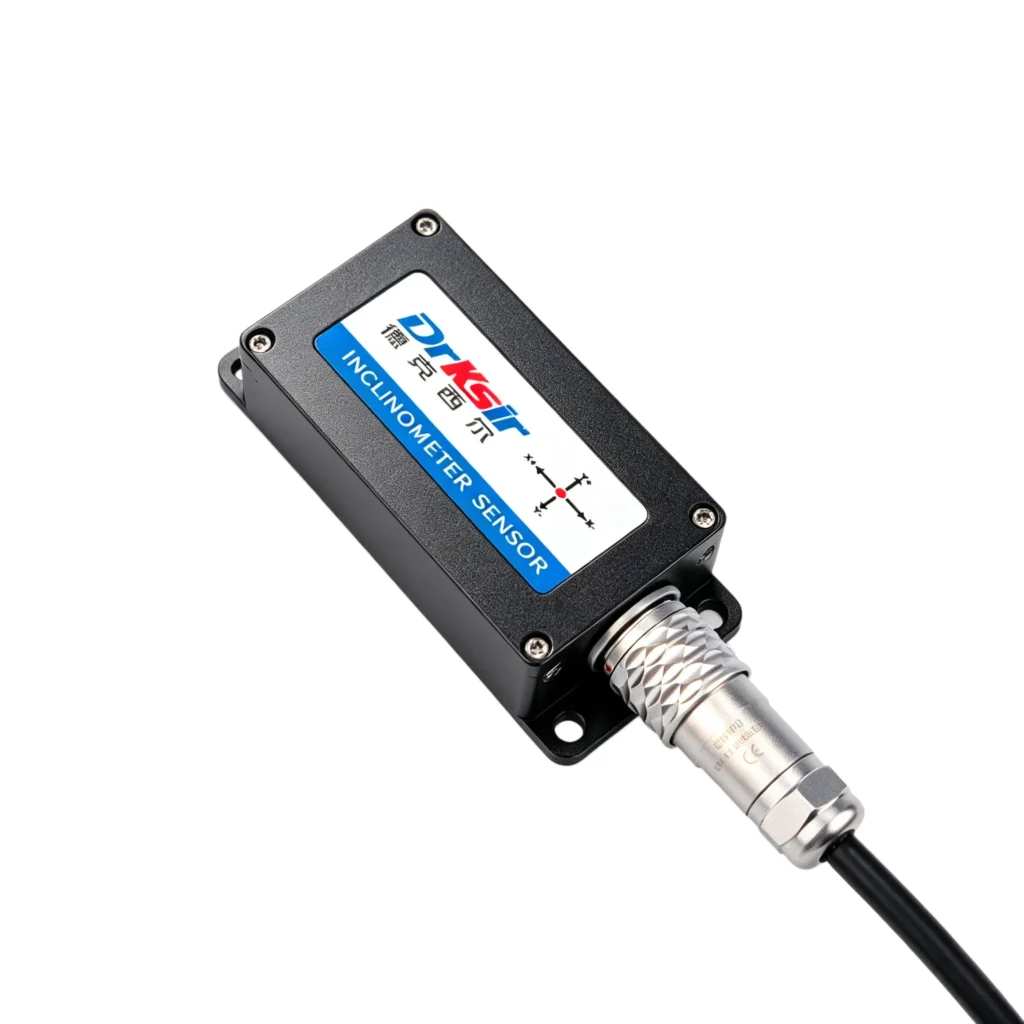
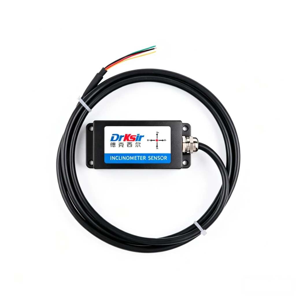
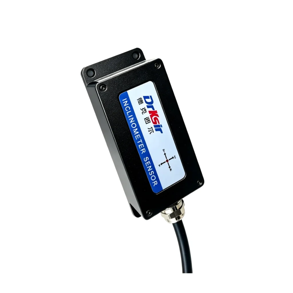
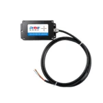
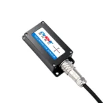
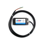
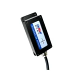
Model: DR-INC-500R
Accuracy: ±0.001° (at room temperature)
Resolution: 0.0005° (at room temperature)
Measuring Range: ±10°
Number of Axes: Dual-axis (X+Y)
Output Interface: RS485, Modbus RTU Protocol
Application Scenarios: Ideal for industrial attitude control in construction machinery, bridge structural monitoring, wind turbine tower monitoring, and other industrial scenarios.
The DR-INC-500-R is a 0.001° ultra-high accuracy RS485 inclinometer engineered for structural health monitoring where micro-deflection matters. Bridges, dams, high-speed rail piers, and tall buildings deform on the order of millidegrees under load, temperature, and wind — well below the resolution of standard industrial tilt sensors. This dual-axis sensor delivers millidegree-class accuracy across a selectable ±5° / ±10° / ±20° / ±30° measuring range, with RS485 output and Modbus RTU protocol for direct integration into SCADA, PLC, or data acquisition systems. The IP67/IP68-rated housing (customizable) and -40°C to +85°C operating range make it suitable for permanent outdoor installation in harsh environments. Default model ships calibrated to ±10°; alternate ranges are configured at the factory on request.
| Item | Parameter |
| Measuring Axis | Dual-axis X & Y |
| Measuring Range | ±5° / ±10° / ±20° / ±30° (Optional) |
| Absolute Accuracy | 0.001°(±5° / ±10°);0.002°(±20°);0.003°(±30°) |
| Resolution | 0.0005° |
| Sampling Frequency | 100Hz |
| Power Supply | DC9~36V |
| Operating Current | 30mA @ DC12V |
| Average Service Life | ≥55,000 hours |
| Communication Interface | RS485 Modbus RTU |
| Operating Temperature | -40℃ ~ +85℃ |
| Protection Grade | IP67 / IP68(Customizable) |
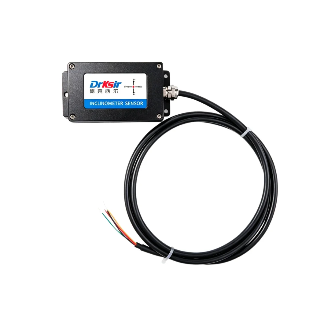
| Cable | Standard 1.5m 4-core shielded cable |
| Net Weight | 280g (without package) |
● Bridge deflection monitoring — continuous tilt tracking on bridge piers, mid-span sections, and expansion joints. Millidegree resolution captures creep, thermal expansion, and post-seismic drift that lower-accuracy sensors miss.
● Dam and reservoir safety — long-term tilt trend analysis on concrete gravity dams, arch dams, and intake towers. The 0.001° absolute accuracy at ±5°/±10° range means seasonal thermal drift stays inside the noise floor.
● High-speed rail pier monitoring — settlement and tilt detection on bridge piers and viaducts under dynamic train loads. 100 Hz sample rate captures transient events during train passage.
● Building settlement — long-term tilt measurement on high-rise structures, particularly during the construction phase and the first 2 years of occupancy.
● Tunnel convergence — cross-section tilt monitoring in metro, railway, and utility tunnels, especially in soft-ground sections.
● 15+ years designing and manufacturing tilt sensors for industrial and infrastructure monitoring
● 3,000+ projects delivered across civil engineering, renewable energy, and transportation
● 0.001° absolute accuracy at the ±5°/±10° range — among the highest-resolution industrial inclinometers in production
● In-house MEMS design and signal conditioning — not a rebranded OEM module
● IP67/IP68 protection options for harsh environment installation
● Average service life ≥55,000 hours (≈ 6.3 years continuous, far longer in typical duty cycles)
● 24-month warranty and lifetime application engineering support
● Versus electrolytic tilt sensors — faster response, no leveling required at install, no fluid temperature sensitivity
● Versus LVDT-based inclinometers — smaller form factor, no moving parts, immune to vibration-induced wear
● Versus consumer-grade MEMS modules — industrial temperature range, calibrated output traceable to NIST standards, IP-rated housing
● Versus competing industrial sensors at the 0.001° spec level — typically 20-40% lower cost with comparable or better absolute accuracy
Mount the sensor on a flat, rigid surface (steel bracket or concrete anchor recommended). For highest accuracy, align the sensor’s X-axis to the primary direction of expected tilt.
The sensor uses a 4-core shielded cable for power and data:
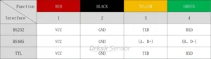
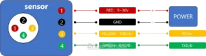
For RS485 cable runs over 100 m, use shielded twisted pair and terminate the shield at one end only. Maximum recommended cable length is 1,200 m at 9600 baud.
Integration & Programming
The sensor communicates via Modbus RTU at default 9600 baud, 8N1. X-axis and Y-axis tilt are returned as register values readable via standard Modbus function codes. Full register map, sample code (C / Python / PLC ladder), and SCADA configuration files are available on request.
OEM/ODM & Customization
Standard units ship from stock within 5 business days. Custom measuring ranges (±5° / ±20° / ±30° alternate to default ±10°), cable lengths, connector types, and protection-grade options (IP67 vs IP68) are available for OEM/ODM orders starting at 50 units. Typical custom lead time is 15-25 business days. Engineering drawings, communication protocol documentation, and integration support are provided free of charge.
Q: Which measuring range should I select?
A: Select the smallest range that covers your expected tilt. The ±5° and ±10° options deliver 0.001° accuracy; ±20° delivers 0.002°; ±30° delivers 0.003°. For bridge and dam monitoring (small deflections), ±5° or ±10° is usually correct. For tower or building monitoring with larger expected movements, ±20° or ±30° may be appropriate. The default SKU ships with ±10°; other ranges are configured at the factory on request (no minimum order quantity for alternate ranges).
Q: Does the sensor require recalibration in the field?
A: No field recalibration is needed for the first 5 years under normal operating conditions. Annual verification against a reference fixture is recommended for sub-millidegree work.
Q: Can the sensor be used in submerged installations?
A: The IP68 protection option covers continuous immersion at 1 m for 30 days. For deeper or longer-term submersion, contact our engineering team for an upgraded sealing option.
Q: What’s the difference between this sensor and the 4-20mA version?
A: Identical mechanics, accuracy, and dimensions. The RS485 version outputs digital data via Modbus RTU; the 4-20mA version outputs a current loop proportional to tilt, preferred where PLC analog inputs are already in place or where long cable runs in electrically noisy environments are required.
Email sales@drksirsensor.com or message us on WhatsApp with your required quantity, measuring range, output interface, and application scenario. We respond within one business day with pricing, datasheet, and lead time.