Description
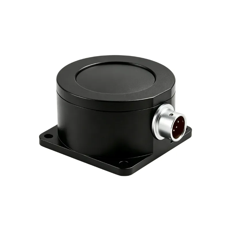
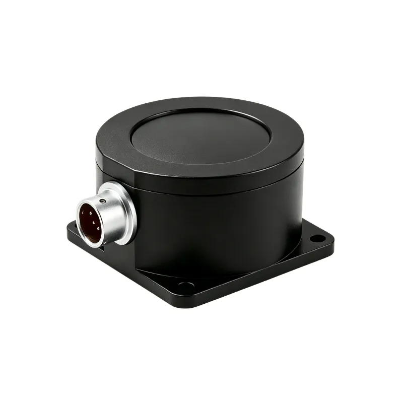
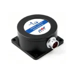
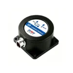
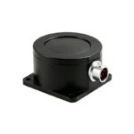
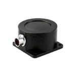
The ±16g 3-Axis Industrial Accelerometer is built for equipment that gets hit. Excavators, rail vehicles, AGVs, stamping presses and off-highway machines generate far more than the low single digits a pump does — shock from travel over rough ground, from load engagement, from the press stroke itself.
At 0.01g accuracy and 0.001g resolution you keep the sensitivity to see real change, while ±16g gives you the headroom to survive the impacts without clipping or saturating. It is the range we suggest whenever the question is “how hard is this machine being worked?” rather than “is this bearing wearing?”. It is the third step in our industrial accelerometers range, covering ±2g through ±32g on one mechanical platform.
Key Specifications
| Parameter |
Specification |
| Measuring Axis |
X, Y, Z (3-axis) |
| Measuring Range |
±16g |
| Absolute Accuracy |
0.01g |
| Resolution |
0.001g |
| Output Options |
CAN / 4-20mA / RS485 (Modbus RTU) / 0-10V |
| Operating Temperature |
-40°C ~ +85°C |
| Protection Grade |
IP67 / IP68 (customizable) |
| Cable |
Standard 1.5m 4-core shielded cable |
| Net Weight |
220g (without package) |
| Average Service Life |
≥55,000 hours |
| — CAN version — |
|
| Communication Interface |
CAN |
| Sampling Frequency |
100Hz |
| Power Supply |
DC 9-36V |
| Operating Current |
30 mA @ DC 12V (CAN variant; other outputs on request) |
Output Options
| Output |
SKU |
Best For |
| CAN |
DR-ACC-16G-N-3X |
Vehicles, mobile machinery, bus networking |
| 4-20mA |
DR-ACC-16G-A-3X |
Long cable runs, direct PLC/SCADA input |
| RS485 (Modbus RTU) |
DR-ACC-16G-R-3X |
Multi-drop digital networks |
| 0-10V |
DR-ACC-16G-C-3X |
Short-distance, cost-sensitive installations |
Typical Applications
- Construction machinery — excavators, loaders, bulldozers, pavers
- Rail vehicle dynamics — ride quality, lateral and vertical acceleration
- AGV and forklift impact logging and collision detection
- Stamping and forging presses — stroke shock and structural loading
- Off-highway and agricultural equipment operating over rough terrain
CAN output is usually the right call here, because most of these machines already run a bus you can join. If your equipment is doing drop tests or crash testing rather than working a shift, the ±32g model is the better fit. For slow, static tilt on the same machine, an inclinometer will be more accurate than an accelerometer.
Why Choose Drksir
- 15+ years building industrial sensors, with 3,000+ projects delivered worldwide
- Factory-calibrated before every shipment — each unit ships with its calibration data
- OEM/ODM available: range, output, cable length, connector and housing can be specified to your machine
- Built for harsh environments: IP67 / IP68 (customizable), -40°C to +85°C operating range
- Engineering support, not just a catalog: tell us your machine, speed, mounting position and what you are trying to catch, and we will tell you which range fits
Frequently Asked Questions
How do I pick the right measuring range? As a working rule, your normal operating acceleration should sit at roughly one-third to one-half of the full range. That leaves headroom for start-up transients and fault conditions without wasting resolution. If your machine normally sees 0.5g, ±2g is right; if it sees 3-4g during normal running, move to ±8g and keep ±16g for shock events.
Which output should I choose? CAN for vehicles and mobile machinery where a bus already exists; 4-20mA for long cable runs and direct PLC/SCADA input; RS485 (Modbus RTU) when you want multiple sensors on one digital network; 0-10V for short, cost-sensitive runs. Our CAN version is in stock now — the other three are available on request.
Can you customize the sensor for our application? Yes. Range, output type, cable length, connector and mounting are all configurable, and we do OEM/ODM runs. Send us the machine type, speed, mounting position, and what you need to detect, and we will come back with a recommendation.
Get a Quote
📧 sales@drksirsensor.com 💬 WhatsApp: +86-135-1581-0281
Not sure which range fits your machine? Contact our engineers — send us the machine type, running speed and mounting position, and we will tell you which model to use before you order.