Project Background
A wind turbine tower is a slender structure carrying a very large mass at the top, and that geometry makes it sensitive to anything that moves the base. Foundation settlement, a soft patch under one leg, or a foundation bolt that has lost its preload all show up first as tilt — a slow lean far too small to see, but large enough to change the load path through the tower and the fatigue duty on the flange joints. Operators monitor tower inclination and foundation tilt for that reason: not to catch a dramatic failure, but to notice a drift early enough to plan an intervention.
The Challenge
- Small movement, tall structure — a fraction of a degree at the base flange becomes a large lateral offset at hub height, so the sensor has to resolve movement in thousandths of a degree.
- Permanent outdoor exposure — sensors sit at the tower base flange, on the foundation ring or inside the tower, facing rain, salt spray, freeze-thaw cycling and summer heat on a steel housing.
- Wide temperature swing — the operating range has to cover a site that runs from well below freezing to direct sun.
- Many towers, one system — a wind farm instruments dozens of turbines, and the owner wants them read through one data acquisition path rather than one analog channel each.
- Access is expensive — sending a crew up a tower or out to a remote ridge just to check a sensor is not a maintenance plan.
The Solution
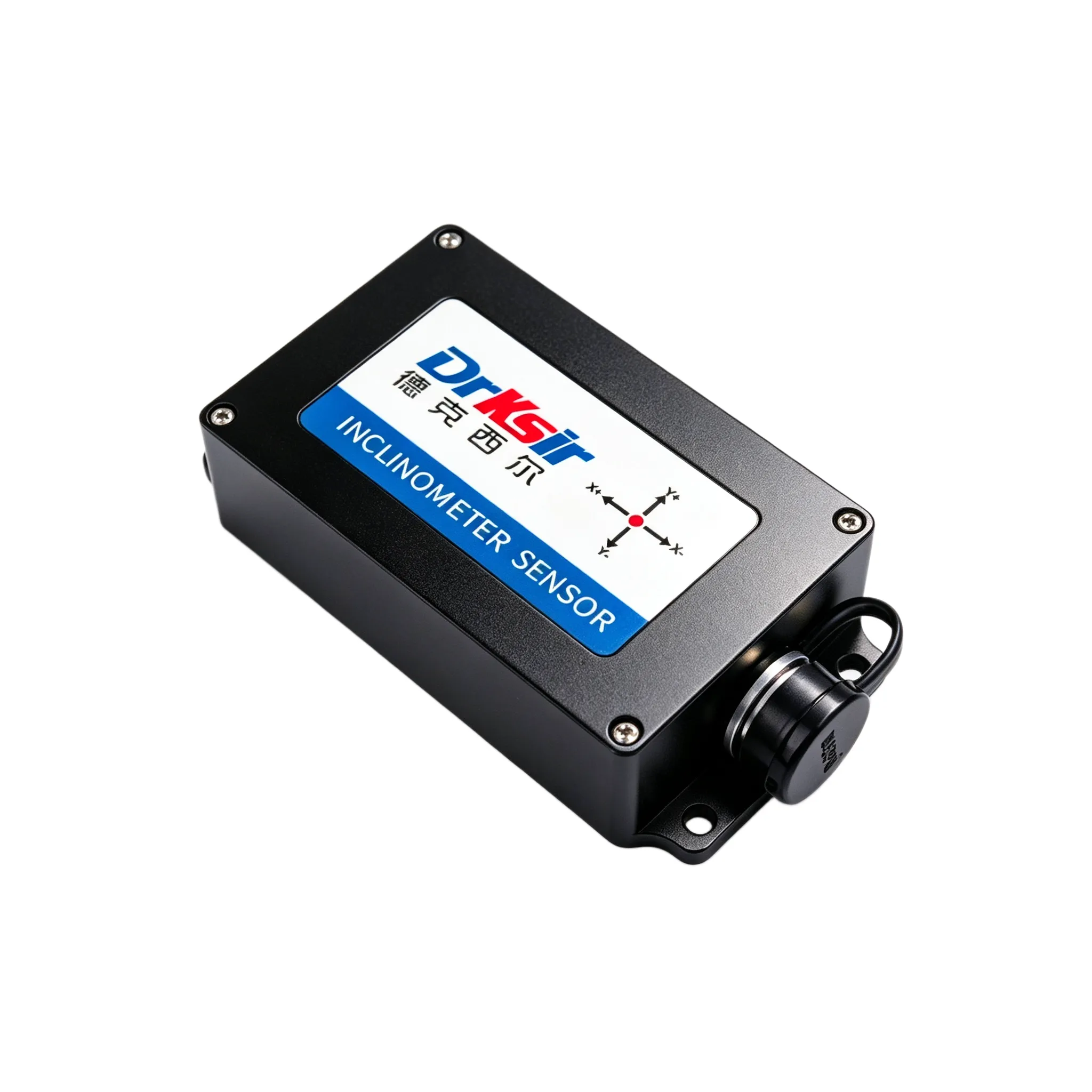
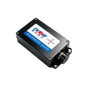
Tower tilt is measured with the DR-INC-300-R-D-30 dual-axis inclinometer, mounted on a machined bracket at the tower base flange and on the foundation ring, with the X-axis aligned to the direction of expected lean. Its 0.005° High-Precision class accuracy is the reason this installation works at all — a general-purpose 0.1° tilt sensor would see only noise where the useful signal sits.
Each sensor is addressed on a shared RS485 bus and polled over Modbus RTU (9600 baud, 8N1), so one trunk line carries every node back to the farm’s SCADA or data logger at a recommended maximum run of 1,200 m. The ±30° default range covers foundation movement, erection tolerance and the tilt that occurs while the tower is being assembled, so the sensor does not clip during commissioning and does not need to be re-ranged afterwards.
Where an operator wants the same measurement at the highest accuracy the line offers — for example on the foundation ring of a tower already showing movement — the DR-INC-500-R-D-10 0.001° unit is used on the same bus with the same mounting practice.
Why This Model
- 0.005° class accuracy resolves the slow lean that matters, across a temperature band of −40 ℃ ~ +85 ℃.
- ±30° measuring range covers base-flange tilt, foundation movement and transport or erection conditions in one part number.
- RS485 / Modbus RTU with addressable nodes lets a whole wind farm share one bus, rather than one analog input per sensor per tower.
- IP67 / IP68 protection (customizable) suits base-level and foundation-ring mounting with no secondary enclosure in most locations.
- 24-month warranty and factory-configurable alternate ranges match a multi-year monitoring programme; where the farm’s system uses analog inputs instead, the mechanically identical DR-INC-300-A-D-30 4-20mA version is a direct substitute.
Results / Outcome
- Tower verticality and foundation tilt are read continuously instead of through periodic manual survey visits.
- A slow lean is visible as a trend line, so it can be reviewed against the design model before it becomes a repair.
- One RS485 trunk serves the turbines on a section, which simplifies cabling and cuts the number of data acquisition channels required.
- The recorded history supports year-on-year comparison and gives the maintenance planner a factual basis for scheduling.
Related Products
- DR-INC-300-R-D-30 — 0.005° High-Precision RS485 Inclinometer
- DR-INC-300-A-D-30 — 0.005° High-Precision 4-20mA Inclinometer
- Browse all industrial inclinometers
- Need a node layout or a range recommendation? Request a quote with your tower height, node count and expected movement.
Get a Quote
Tell us your tower height, node count and expected movement and we will recommend a measuring range and an output, then quote it.
📧 Email: sales@drksirsensor.com | 💬 WhatsApp: +86-135-1581-0281