Project Background
Bridges deform continuously. Traffic loading, seasonal temperature swings, wind and post-seismic settling all move a structure at the millidegree level — movements far too small for the crack gauges and visual inspections that many asset owners still rely on. For long-span and high-value structures, the monitoring requirement is not “has it moved a lot” but “is the movement drifting in a way that does not match the design model.” That question can only be answered with a sensor whose noise floor sits below the movement it is trying to see.
The Challenge
- Resolution requirement — the movements of interest are in the millidegree range; a conventional 0.1° industrial tilt sensor cannot resolve them at all.
- Permanent outdoor duty — the sensor is installed at pier caps, mid-span soffits and expansion joints, exposed to rain, freeze-thaw cycling and direct sun for years.
- Long cable runs — instrument cabinets typically sit at the abutment or in a nearby control room, often 200–800 m from the farthest sensor.
- Multi-sensor networks — a single bridge monitoring layout commonly uses 10–40 tilt nodes along the deck and piers, which must be read from one data acquisition system.
- Baseline stability — a sensor that drifts over time corrupts the long-term trend, which is the entire point of the installation.
The Solution
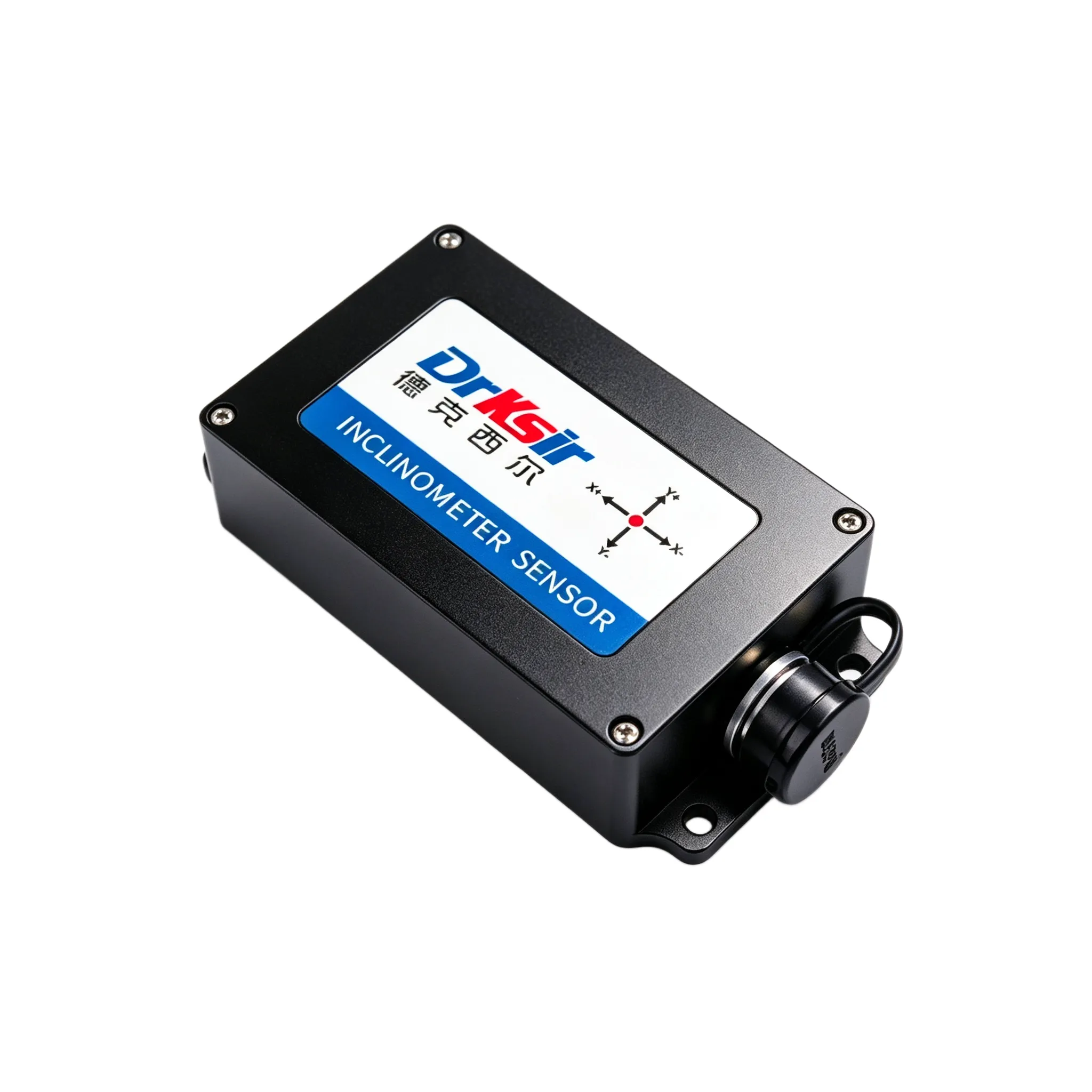
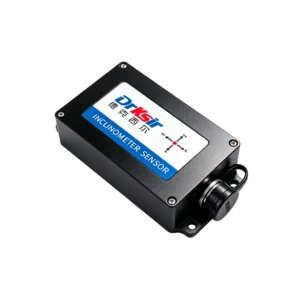
The project uses the DR-INC-500-R-D-10 dual-axis inclinometer at each monitoring node, configured at the factory to the ±10° range (alternate ±5° / ±20° / ±30° ranges are available and are set per node depending on expected movement). The sensor delivers 0.001° absolute accuracy at the ±5° / ±10° range with a 0.0005° resolution — roughly two orders of magnitude finer than general-purpose tilt sensors — and a 100 Hz sampling frequency so short transient events during heavy vehicle passage are captured rather than averaged away.
Each node is mounted on a machined steel bracket or chemical anchor, with the X-axis aligned to the primary direction of expected tilt. All sensors are wired onto a single RS485 bus and polled over Modbus RTU at 9600 baud, 8N1, which lets the owner’s SCADA or data logger read every node through one trunk line at a maximum recommended run of 1,200 m — comfortably covering a full bridge span.
Why This Model
- 0.001° class accuracy at the ±5°/±10° range keeps seasonal thermal drift inside the noise floor, so the long-term trend line stays meaningful.
- RS485 / Modbus RTU with addressable nodes — multiple sensors share one bus and one data acquisition channel, avoiding a separate analog input per node.
- IP67 / IP68 protection (customizable) and −40 ℃ ~ +85 ℃ operating range support permanent outdoor installation without a secondary enclosure in most locations.
- ≥55,000 hours average service life and 4-core shielded cable (1.5 m standard) suit long-term infrastructure deployments where re-visiting a pier cap is expensive.
- Where the owner’s data system uses analog inputs instead of a digital bus, the mechanically identical DR-INC-500-A-D-10 4-20mA version is a drop-in alternative.
Results / Outcome
- Continuous, automated tilt readings replace periodic manual inspection, so the trend is visible between site visits rather than only during them.
- Millidegree-class resolution makes it possible to distinguish normal thermal movement from genuine structural drift.
- One RS485 trunk reads the entire node network, simplifying cabling and reducing the number of data acquisition channels required.
- The long-term baseline is stable enough to support year-on-year comparison against the design model.
Related Products
- Need a layout review or a range recommendation? Request a quote with your span, node count and expected movement.
Get a Quote
Tell us your span, node count and expected movement and we will recommend a measuring range and an output, then quote it.
📧 Email: sales@drksirsensor.com | 💬 WhatsApp: +86-135-1581-0281