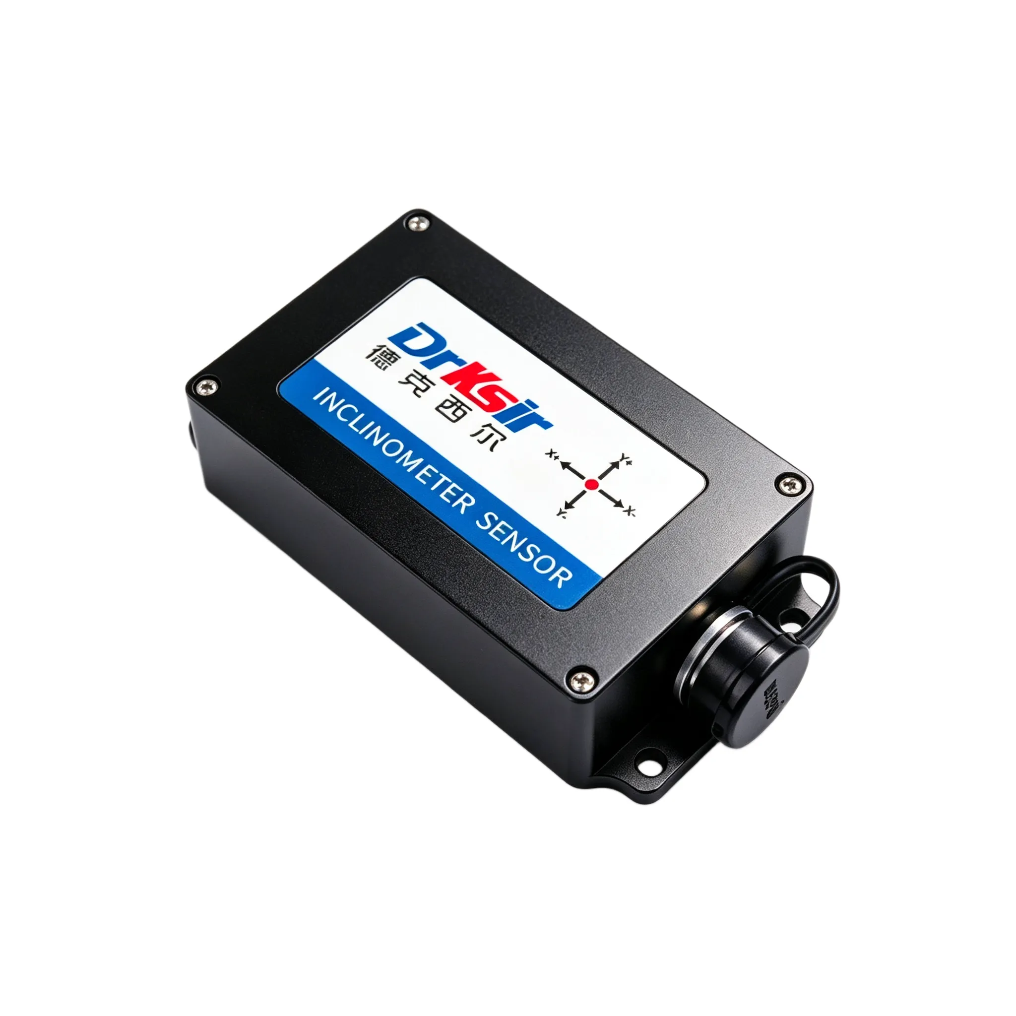
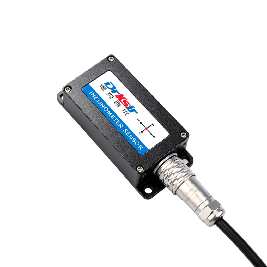
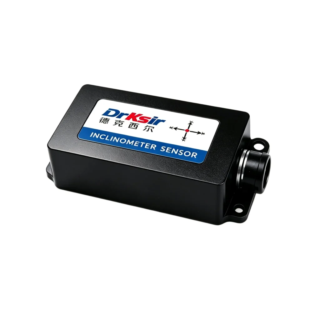
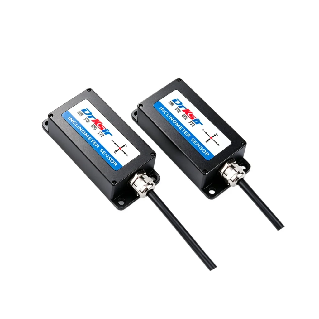
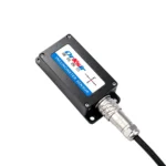
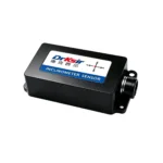
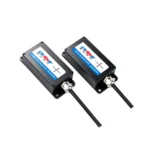
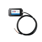
Model: DR-INC-300A
Accuracy: ±0.005° (at room temperature)
Resolution: 0.0007° (at room temperature)
Measuring Range: ±30°
Number of Axes: Dual-axis (X+Y)
Output Interface: 4~20mA
Application Scenarios: Ideal for industrial attitude control in construction machinery, bridge structural monitoring, wind turbine tower monitoring, and other industrial scenarios.
The DR-INC-300-A is a high-precision inclinometer with 0.005° absolute accuracy and 4-20mA output, built for tower monitoring systems that already use PLC analog inputs or current-loop data loggers. This high-precision inclinometer outputs two independent 4-20mA loops proportional to X and Y tilt across a selectable ±5° / ±10° / ±20° / ±30° range. The current loop holds its value across long cable runs in electrically noisy plants, which suits retrofit projects where protocol converters are not welcome. The IP67 / IP68 (customizable) housing and -40°C ~ +85°C rating allow permanent mounting on wind turbine towers, transmission masts, and industrial structures.
| Parameter | Specification |
| Measuring Axis | Dual-axis X & Y |
| Measuring Range | ±5° / ±10° / ±20° / ±30° (optional, default ±30°) |
| Absolute Accuracy | 0.005° |
| Resolution | 0.0007° |
| Sampling Frequency | 100 Hz |
| Power Supply | DC 11~36V |
| Operating Current | 50 mA @ DC 12V |
| Communication Interface | 4-20mA current loop (2 channels: X-axis, Y-axis) |
| Operating Temperature | -40°C ~ +85°C |
| Protection Grade | IP67 / IP68 (customizable) |
| Average Service Life | ≥55,000 hours |
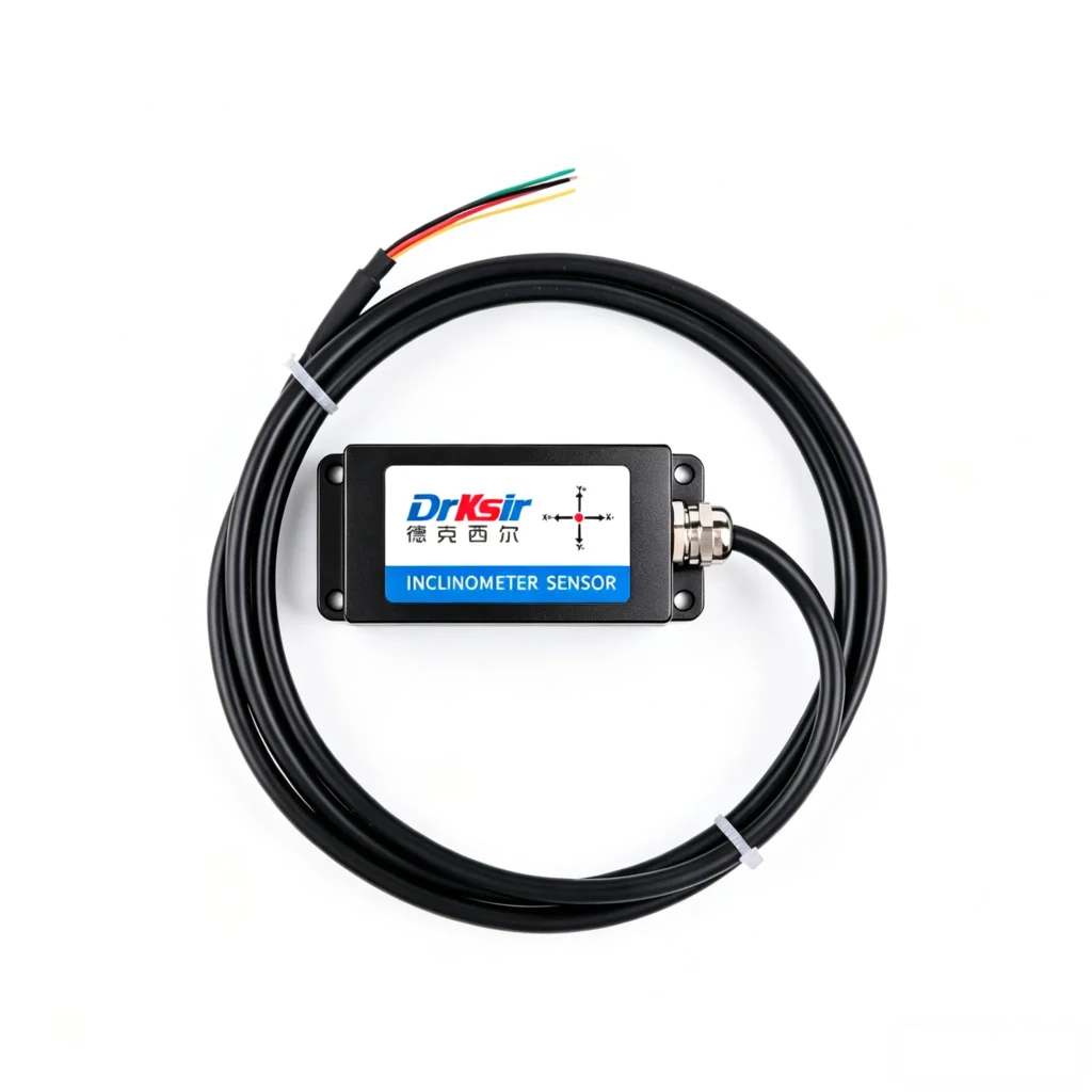
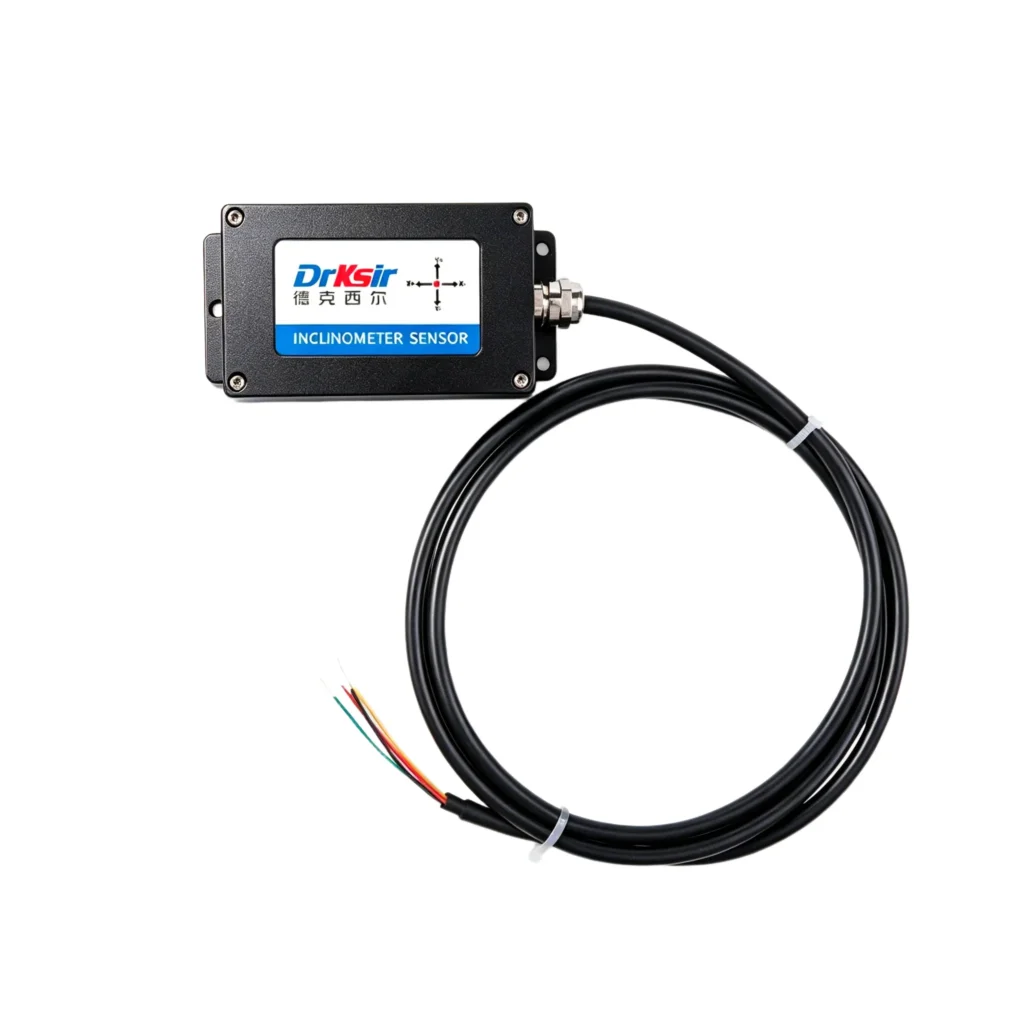
| Cable | Standard 1.5 m 6-core shielded cable (red/black power, yellow/green reserved RS485 configuration, white X output, brown Y output) |
Mount on a flat, rigid surface (steel bracket or concrete anchor recommended). For highest accuracy, align the sensor’s X-axis to the primary direction of expected tilt.
The 4-20mA version uses a 6-core shielded cable, with a different wire-to-function mapping from the RS485 version:

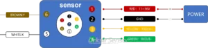
Two independent 4-20mA loops are output on the white and brown wires, one per axis. Each loop draws 4 mA at negative full-scale tilt, 12 mA at zero tilt, and 20 mA at positive full-scale tilt. Polarity is reversible via the configuration utility on the reserved yellow/green pair.
For installations near VFDs, motor starters, or welding equipment, keep the loop cable at least 200 mm from power cables and cross them at 90° if they must intersect. Maximum recommended cable length depends on loop supply voltage and load resistance — refer to the datasheet for the loop resistance budget at a given supply voltage.
The 4-20mA output needs no protocol converter or configuration software in normal operation. Connect the white and brown wires to any 4-20mA analog input module, scale the reading according to the PLC’s input range, and the tilt value is available immediately:
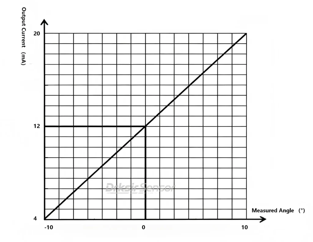
For a ±30° sensor at default calibration: 4 mA = -30°, 12 mA = 0°, 20 mA = +30°. Most PLC analog input modules accept 4-20mA directly with no additional hardware.
OEM/ODM & Customization
Standard units ship from stock within 5 business days. Custom measuring ranges (±5° / ±10° / ±20° alternate to default ±30°), cable lengths, connector types, and protection-grade options (IP67 vs IP68) are available for OEM/ODM orders starting at 50 units. Typical custom lead time is 15-25 business days.
FAQ
Q: When should I choose the 4-20mA version over the RS485 version?
A: Choose 4-20mA when the data acquisition system uses analog inputs, when cable runs exceed 500 m, or when the installation environment has high EMI from VFDs or motors. Choose RS485 when several sensors share one bus, when you need digital diagnostics, or when the reading must be transmitted without an analog conversion step.
Q: Which measuring range should I select?
A: Select the smallest range that covers your expected tilt. Accuracy stays at 0.005° across all four options (±5° / ±10° / ±20° / ±30°), so the choice is about arc, not precision. The default SKU ships with ±30°; other ranges are configured at the factory on request.
Q: What if I need a different accuracy or measuring range?
A: The wired inclinometer family covers 0.1° to 0.001°, all available with 4-20mA output. For sub-millidegree structural work, step up to the 0.001° Ultra-High Accuracy 4-20mA Inclinometer (±5° / ±10° / ±20° / ±30°, 0.0005° resolution). For a wider arc on construction machinery, the 0.01° Industrial-Grade 4-20mA Inclinometer measures ±10° / ±30° / ±60° / ±90°. For general leveling at ±90°, the 0.1° General-Purpose 4-20mA Inclinometer is the lower-cost entry point.
Q: What’s the difference between this sensor and the RS485 version?
A: Identical mechanics, accuracy, and dimensions. The 4-20mA version outputs a current loop proportional to tilt and needs no protocol converter; the 0.005° High-Precision RS485 Inclinometer returns digital values over Modbus RTU and allows multiple sensors on one bus.
Q: Does the sensor require recalibration in the field?
A: No field recalibration is required for normal operation. For safety-critical tower or structural work we recommend periodic verification against a reference fixture; the interval depends on your monitoring standard.
Get a Quote
📧 Email: sales@drksirsensor.com | 💬 WhatsApp: +86-135-1581-0281
Send us your required quantity, measuring range, output interface, and application scenario. We respond within one business day with pricing, datasheet, and lead time.