Project Background
Concrete gravity dams, arch dams and intake towers are monitored for tilt because a slow, systematic rotation is one of the earliest measurable signs of a developing problem — long before visible cracking. Dam safety instrumentation is also unusually conservative about signal transmission: most dam monitoring systems were specified around 4-20mA current loops decades ago and are deliberately kept that way, because a current loop degrades gracefully, tolerates long cable runs and interfaces with almost any data logger or PLC analog card.
The Challenge
- Very long cable runs — sensors sit on the dam crest, on galleries inside the structure, or on intake towers; the control room may be several hundred meters away or more.
- Electrically noisy environment — large motors, gate actuators and switchgear sit close to instrument cabling.
- Legacy data acquisition — the existing monitoring system accepts 4-20mA analog inputs and is not being replaced.
- Finest resolution required — dam movement of interest is in the millidegree range, which rules out general-purpose current-loop tilt sensors.
- Decades of service — the sensor must survive permanently wet, humid and temperature-cycling conditions with no field maintenance.
The Solution
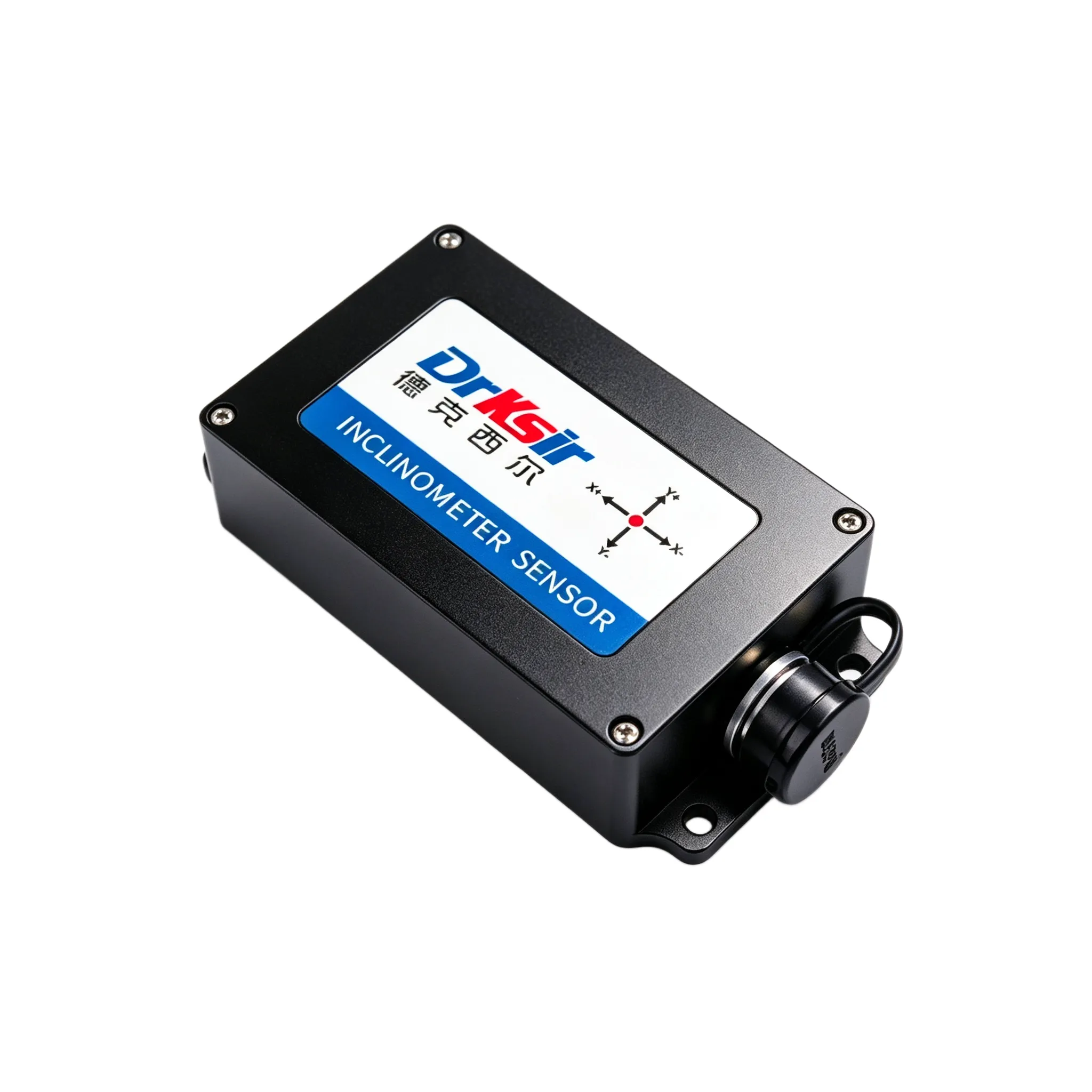
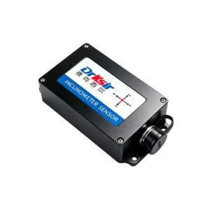
Each monitoring point uses the DR-INC-500-A-D-10 dual-axis 4-20mA inclinometer, factory-configured to the ±10° range by default with ±5° / ±20° / ±30° options available per node. Two independent current loops carry X-axis and Y-axis tilt on the white and brown wires respectively, so a single sensor delivers both axes to two analog input channels with no protocol converter.
At default calibration on a ±10° unit, 4 mA = −10°, 12 mA = 0°, 20 mA = +10°. The tilt value is recovered by the standard scaling used in the owner’s PLC or logger。
Because the signal is a current loop rather than a voltage, loop resistance does not degrade the reading with distance, which is why this variant is preferred on dam installations where the run from gallery to control room is measured in hundreds of meters. For runs that pass near VFDs, gate drives or welding equipment, the loop cable is kept at least 200 mm from power cabling and crossed at 90° where it must intersect.
The sensor’s 0.001° absolute accuracy at the ±5°/±10° range and 0.0005° resolution are identical to the RS485 version — the two models differ only in output format, not in mechanics or accuracy.
Why This Model
- 4-20mA current loop output integrates directly with existing dam-safety data loggers and PLC analog cards — no protocol converter, no firmware work.
- Immune to voltage drop over long runs, unlike 0-10 V output sensors, and inherently tolerant of ground loops.
- Two independent loops cover both X and Y axes from one sensor, halving the sensor count for a two-axis node.
- 0.001° accuracy class is what makes the installation useful — lower-accuracy 0.1°–0.5° current-loop sensors cannot resolve the movement being measured.
- IP67 / IP68 (customizable), −40 ℃ ~ +85 ℃, DC 11~36 V supply, ≥55,000 hours service life, 24-month warranty.
Results / Outcome
- Existing 4-20mA monitoring infrastructure is reused as-is, so no signal conversion hardware is added.
- Tilt data arrives at the control room without degradation across long cable distances.
- Millidegree resolution allows seasonal thermal behaviour to be separated from structural deformation trends.
- The current-loop output gives operators a familiar, conservative signal format consistent with the rest of the dam’s instrumentation.
Related Products
- DR-INC-500-A-D-10 — 0.001° Ultra-High Accuracy 4-20mA Inclinometer
- DR-INC-500-R-D-10 — 0.001° Ultra-High Accuracy RS485 Inclinometer
- Browse all industrial inclinometers
- Tell us your loop supply voltage and run length and we will check the resistance budget. Request a quote.
Get a Quote
Send us your loop supply voltage, run length and the analog input module you are using and we will confirm the scaling and the resistance budget.
📧 Email: sales@drksirsensor.com | 💬 WhatsApp: +86-135-1581-0281