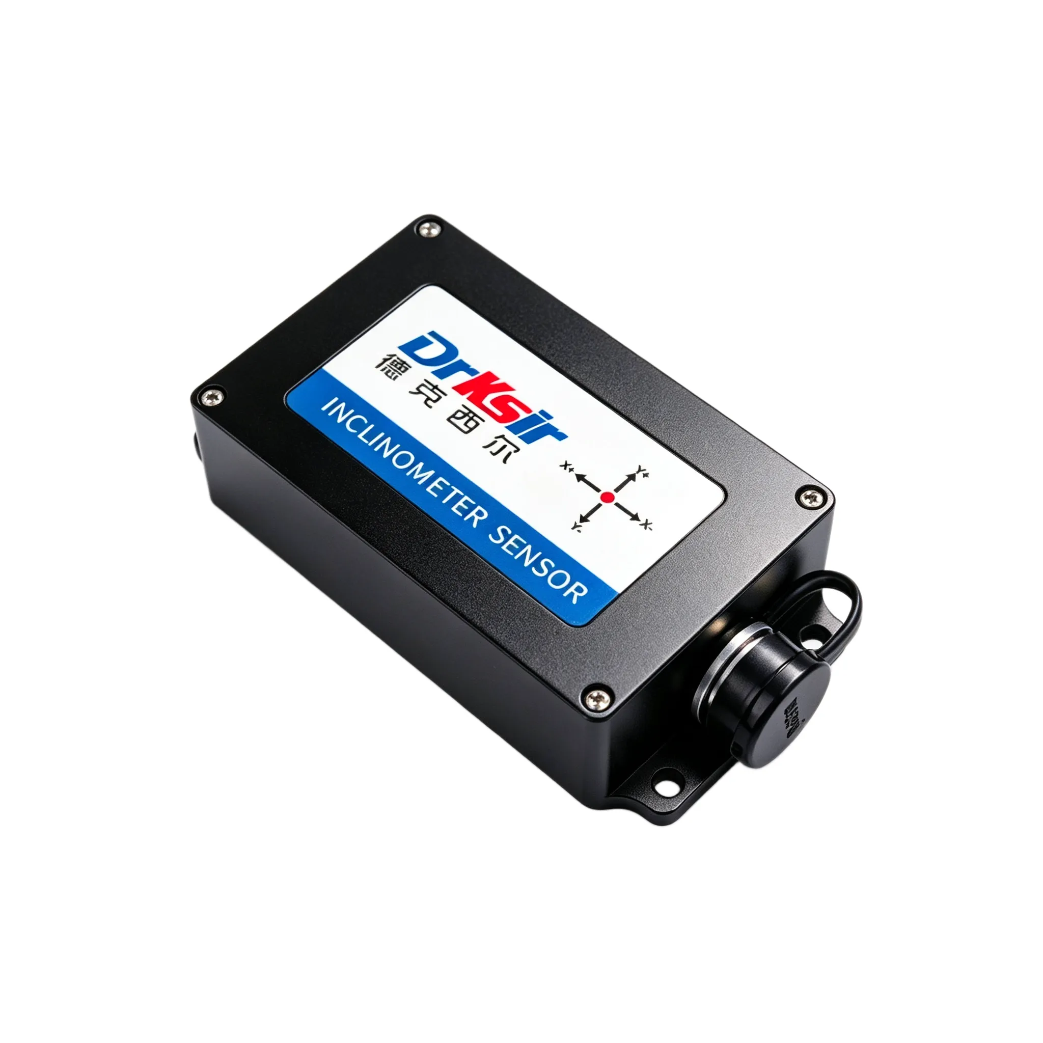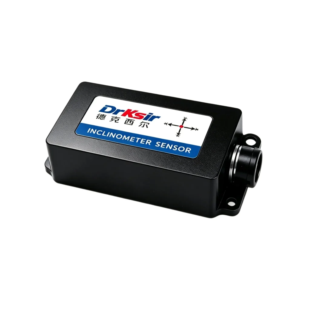
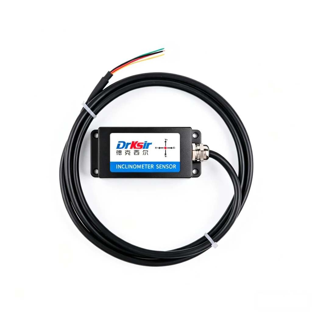
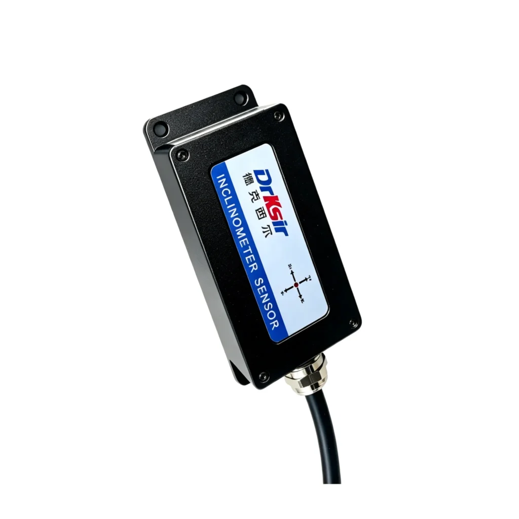
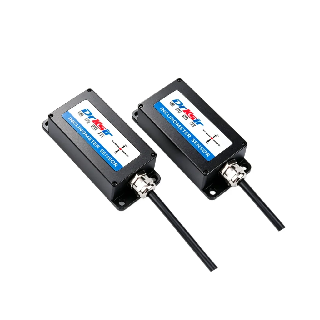
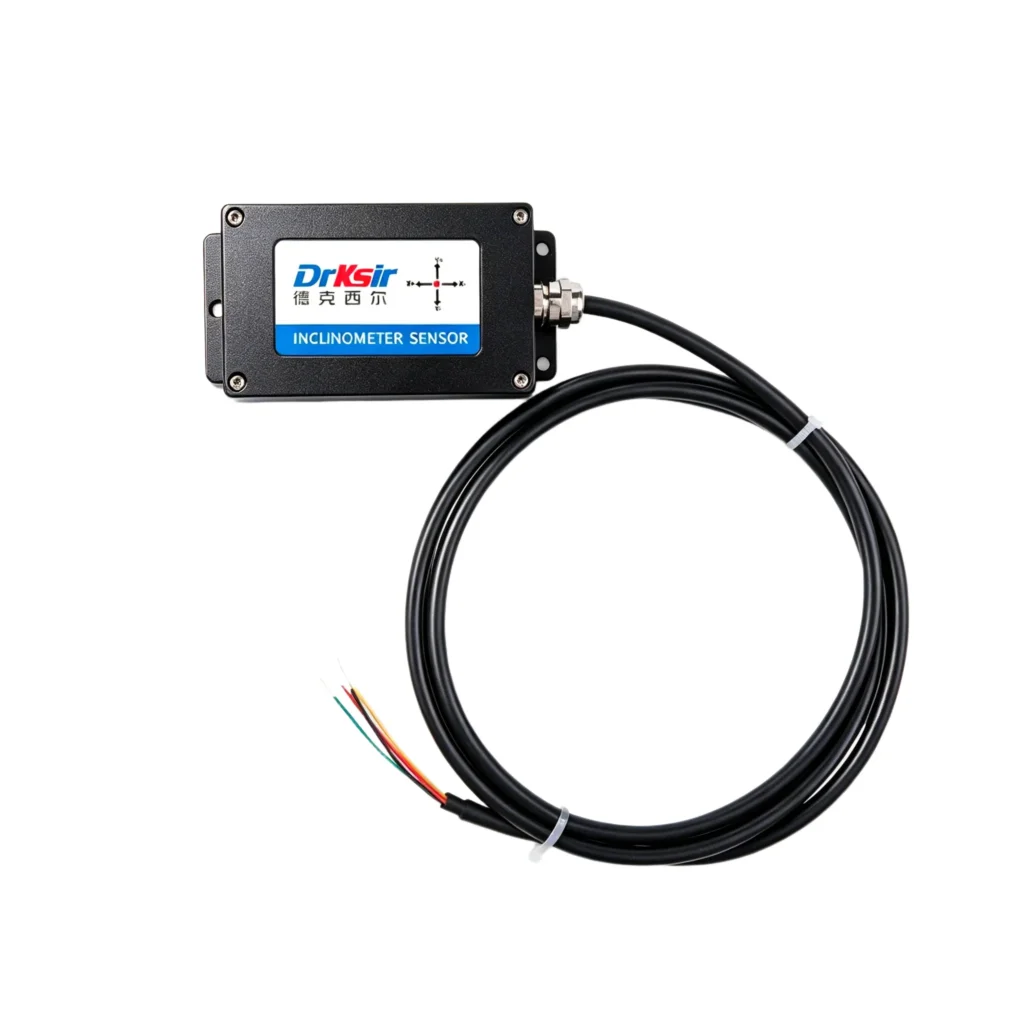
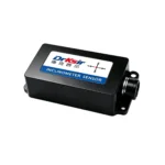
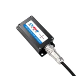
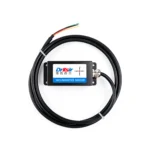
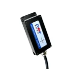
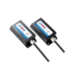
Model: DR-INC-100R
Accuracy: ±0.1° (at room temperature)
Resolution: 0.01° (at room temperature)
Measuring Range: ±90°
Number of Axes: Dual-axis (X+Y)
Output Interface: RS485, Modbus RTU Protocol
Application Scenarios: Ideal for industrial attitude control in construction machinery, bridge structural monitoring, wind turbine tower monitoring, and other industrial scenarios.
The DR-INC-100-R-D-90-IP68 is a general-purpose inclinometer with 0.1° absolute accuracy and RS485 output, for applications that need full-range angle feedback rather than laboratory precision. This general-purpose inclinometer covers ±10° / ±30° / ±60° / ±90° with 0.1° absolute accuracy, 0.01° resolution, and 100 Hz output, which suits vehicle leveling, aerial platform tilt, solar tracker angle, and general attitude control. Modbus RTU keeps the harness to one shielded pair, and the IP67 / IP68 (customizable) housing with a -40°C ~ +85°C rating works outdoors on a mast, a chassis, or a tracker frame.
| Parameter | Specification |
| Measuring Axis | Dual-axis X & Y |
| Measuring Range | ±10° / ±30° / ±60° / ±90° (optional, default ±90°) |
| Absolute Accuracy | 0.1° |
| Resolution | 0.01° |
| Sampling Frequency | 100 Hz |
| Power Supply | DC 9~36V |
| Operating Current | 30 mA @ DC 12V |
| Communication Interface | RS485 (Modbus RTU) |
| Operating Temperature | -40°C ~ +85°C |
| Protection Grade | IP67 / IP68 (customizable) |
| Average Service Life | ≥55,000 hours |
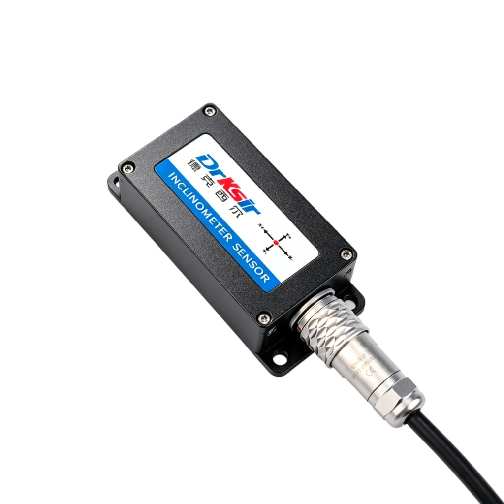
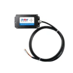
| Cable | Standard 1.5 m 4-core shielded cable |
Mount the sensor on a flat, rigid surface (steel bracket or concrete anchor recommended). For highest accuracy, align the sensor’s X-axis to the primary direction of expected tilt.
The sensor uses a 4-core shielded cable for power and data:
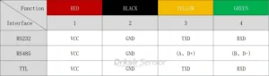
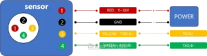
For RS485 cable runs over 100 m, use shielded twisted pair and terminate the shield at one end only. Maximum recommended cable length is 1,200 m at 9600 baud.
Standard units ship from stock within 5 business days. Custom measuring ranges (±10° / ±30° / ±60° alternate to default ±90°), cable lengths, connector types, and protection-grade options (IP67 vs IP68) are available for OEM/ODM orders starting at 50 units. Typical custom lead time is 15-25 business days. Engineering drawings and integration support are provided free of charge.
Q: Which measuring range should I select?
A: Select the smallest range that covers your expected travel. Accuracy is 0.1° across all four options (±10° / ±30° / ±60° / ±90°), so the choice is about arc, not precision. The ±90° default suits vehicle leveling and platform work that uses the full mechanical travel; a mast or frame that stays within a few degrees can use a narrower range. The default SKU ships with ±90°; other ranges are configured at the factory on request.
Q: What if I need higher accuracy?
A: The wired inclinometer family covers 0.1° to 0.001° in one housing family. For a wider arc at tighter accuracy, the 0.01° Industrial-Grade RS485 Inclinometer holds 0.01° at ±10° and ±30°. For tower and machine work, the 0.005° High-Precision RS485 Inclinometer holds 0.005° across ±5° to ±30°. For sub-millidegree structural monitoring, the 0.001° Ultra-High Accuracy RS485 Inclinometer reaches 0.0005° resolution.
Q: What’s the difference between this sensor and the 4-20mA version?
A: Identical mechanics, accuracy, and dimensions. The RS485 version returns digital values over Modbus RTU and allows several sensors on one bus; the 0.1° General-Purpose 4-20mA Inclinometer outputs a current loop proportional to tilt, preferred where the controller only has analog inputs.
Q: Does the sensor require recalibration in the field?
A: No field recalibration is required for normal operation. Periodic verification against a reference fixture is good practice on any safety-related installation; the interval depends on your site standard.
Q: Can the sensor be used in submerged installations?
A: The IP68 protection option (customizable) is specified for continuous immersion. The qualified depth and duration depend on the sealing configuration — request the datasheet for the figures for your installation.
📧 Email: sales@drksirsensor.com | 💬 WhatsApp: +86-135-1581-0281
Send us your required quantity, measuring range, output interface, and application scenario. We respond within one business day with pricing, datasheet, and lead time.